GPIO 应用
Author:余生
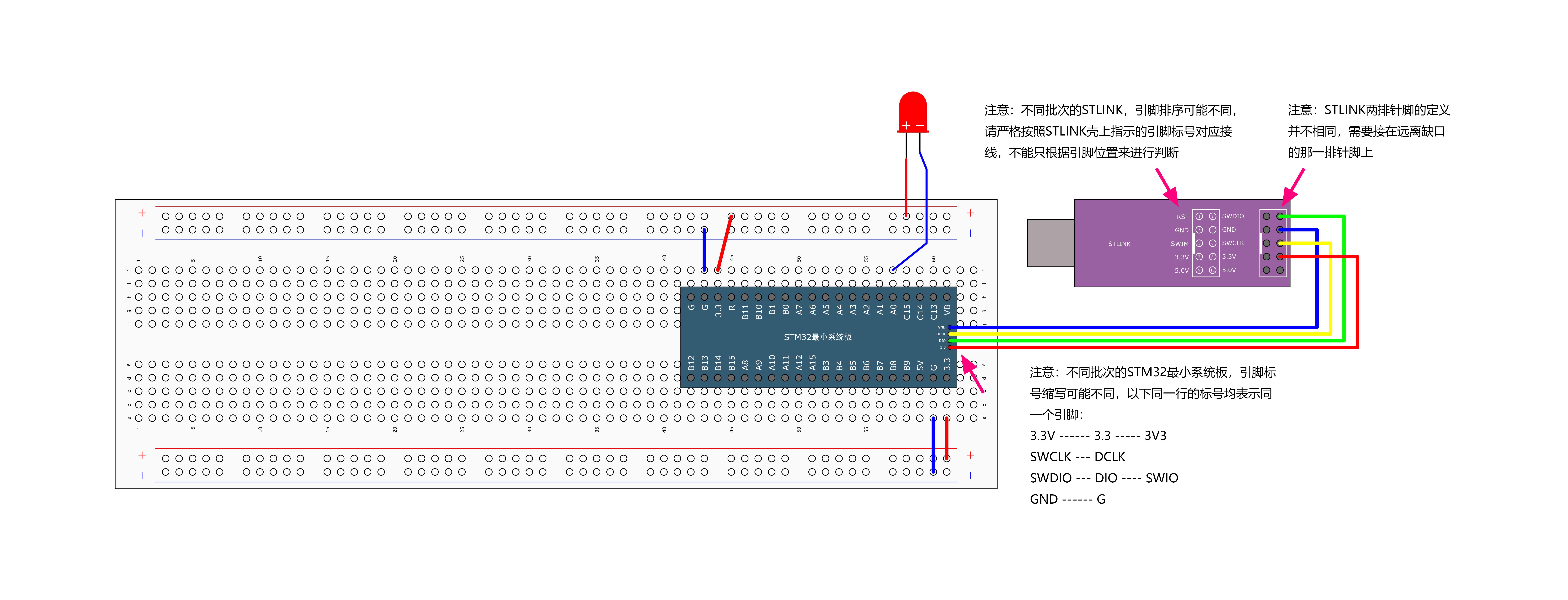
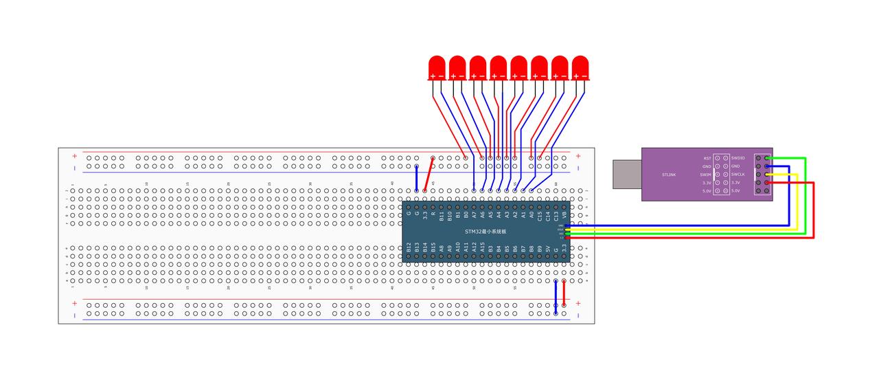
一、硬件连接

二、GPIO 基本代码编写
STM32 GPIO 配置步骤
1. 使能时钟
在使用任何外设之前,需要先开启其对应的时钟。例如,如果要使用 GPIOC,则需要开启 GPIOC 的时钟。
cpp
RCC_APB2PeriphClockCmd(RCC_APB2Periph_GPIOC, ENABLE);1
2. 配置 GPIO 模式
根据应用需求选择 GPIO 的工作模式(输入或输出)。这里以设置 GPIOC 的第 13 号引脚为例,将其配置为推挽输出模式,速度为 50MHz。
cpp
GPIO_InitTypeDef GPIO_InitStructure;
GPIO_InitStructure.GPIO_Mode = GPIO_Mode_Out_PP; // 推挽输出模式
GPIO_InitStructure.GPIO_Pin = GPIO_Pin_13;       // 指定使用的引脚
GPIO_InitStructure.GPIO_Speed = GPIO_Speed_50MHz;// 设置输出速度
GPIO_Init(GPIOC, &GPIO_InitStructure);           // 初始化GPIOC
1
2
3
4
5
2
3
4
5
3. 控制 GPIO 电平
设置高电平
使用 GPIO_SetBits() 函数将指定引脚置为高电平。
cpp
GPIO_SetBits(GPIOC, GPIO_Pin_13); // 将PC13置为高电平1
设置低电平
使用 GPIO_ResetBits() 函数将指定引脚置为低电平。
cpp
GPIO_ResetBits(GPIOC, GPIO_Pin_13); // 将PC13置为低电平1
4. 读取 GPIO 电平
使用 GPIO_ReadInputDataBit() 函数读取指定引脚的电平状态。
cpp
uint8_t pinState = GPIO_ReadInputDataBit(GPIOC, GPIO_Pin_13);  // 读取PC13的状态
if (pinState == Bit_SET) {
    // PC13处于高电平
} else {
    // PC13处于低电平
}
1
2
3
4
5
6
2
3
4
5
6
完整示例代码
下面是一个完整的例子,演示如何点亮一个连接到 STM32 开发板上 GPIOA 第 0 号引脚的 LED 灯并使其闪烁:
cpp
#include "Delay.h"
#include "stm32f10x.h"  // Device header

int main(void) {
    RCC_APB2PeriphClockCmd(RCC_APB2Periph_GPIOA, ENABLE);

    GPIO_InitTypeDef GPIO_InitStructure;
    GPIO_InitStructure.GPIO_Mode = GPIO_Mode_Out_PP;
    GPIO_InitStructure.GPIO_Pin = GPIO_Pin_0;
    GPIO_InitStructure.GPIO_Speed = GPIO_Speed_50MHz;
    GPIO_Init(GPIOA, &GPIO_InitStructure);

    while (1) {
        GPIO_ResetBits(GPIOA, GPIO_Pin_0);
        Delay_ms(500);
        GPIO_SetBits(GPIOA, GPIO_Pin_0);
        Delay_ms(500);

        GPIO_WriteBit(GPIOA, GPIO_Pin_0, Bit_RESET);
        Delay_ms(500);
        GPIO_WriteBit(GPIOA, GPIO_Pin_0, Bit_SET);
        Delay_ms(500);

        GPIO_WriteBit(GPIOA, GPIO_Pin_0, (BitAction)0);
        Delay_ms(500);
        GPIO_WriteBit(GPIOA, GPIO_Pin_0, (BitAction)1);
        Delay_ms(500);
    }
}
1
2
3
4
5
6
7
8
9
10
11
12
13
14
15
16
17
18
19
20
21
22
23
24
25
26
27
28
29
2
3
4
5
6
7
8
9
10
11
12
13
14
15
16
17
18
19
20
21
22
23
24
25
26
27
28
29
三、练习:流水灯
根据上面知识,实现用多个 led 灯交替闪烁
答案如下,仅作参考

cpp
#include "Delay.h"
#include "stm32f10x.h"  // Device header

int main(void) {
    RCC_APB2PeriphClockCmd(RCC_APB2Periph_GPIOA, ENABLE);

    GPIO_InitTypeDef GPIO_InitStructure;
    GPIO_InitStructure.GPIO_Mode = GPIO_Mode_Out_PP;
    GPIO_InitStructure.GPIO_Pin = GPIO_Pin_All;
    GPIO_InitStructure.GPIO_Speed = GPIO_Speed_50MHz;
    GPIO_Init(GPIOA, &GPIO_InitStructure);

    while (1) {
        GPIO_Write(GPIOA, ~0x0001);  // 0000 0000 0000 0001
        Delay_ms(100);
        GPIO_Write(GPIOA, ~0x0002);  // 0000 0000 0000 0010
        Delay_ms(100);
        GPIO_Write(GPIOA, ~0x0004);  // 0000 0000 0000 0100
        Delay_ms(100);
        GPIO_Write(GPIOA, ~0x0008);  // 0000 0000 0000 1000
        Delay_ms(100);
        GPIO_Write(GPIOA, ~0x0010);  // 0000 0000 0001 0000
        Delay_ms(100);
        GPIO_Write(GPIOA, ~0x0020);  // 0000 0000 0010 0000
        Delay_ms(100);
        GPIO_Write(GPIOA, ~0x0040);  // 0000 0000 0100 0000
        Delay_ms(100);
        GPIO_Write(GPIOA, ~0x0080);  // 0000 0000 1000 0000
        Delay_ms(100);
    }
}
1
2
3
4
5
6
7
8
9
10
11
12
13
14
15
16
17
18
19
20
21
22
23
24
25
26
27
28
29
30
31
2
3
4
5
6
7
8
9
10
11
12
13
14
15
16
17
18
19
20
21
22
23
24
25
26
27
28
29
30
31